Technical brief Power architecture

Parallel BESS vs.
Double-Conversion AI UPS™

Power quality, dynamic response, and data center resilience

Both architectures hold steady state.

They diverge the moment something moves: a GPU cluster ramps, or the grid sags. This brief walks through exactly where they diverge, and why it matters for an AI factory.

01 The problem

Two answers to the same volatility

AI data centers introduce extreme, high-frequency load volatility, and traditional energy architectures are being reevaluated against it. Two competing approaches have emerged: the parallel BESS—a grid-interactive system, whether grid-following, grid-forming, or switching between the two—and the double-conversion AI UPS, the ON.energy architecture.

Both can maintain steady-state operation. Where they diverge significantly is in transient performance, disturbance response, and system integration complexity. This brief shows five things:

  1. 01

    Parallel BESS architectures introduce unavoidable transient deviations, estimated at 1-2 cycles, during high-ramp events.

  2. 02

    Those deviations may be tolerable on stiff grids, but they create power-quality risk on weak or islanded systems.

  3. 03

    Handling grid disturbances with a parallel BESS forces an operational conflict: support the load, or stay interconnection-compliant.

  4. 04

    The hybrid workaround, BESS plus low-voltage UPS, significantly increases cost, complexity, and failure modes.

  5. 05

    A double-conversion AI UPS fully decouples the load, eliminating transient propagation, and simplifies interconnection modeling and approval.

02 Architecture

Where the battery sits changes everything

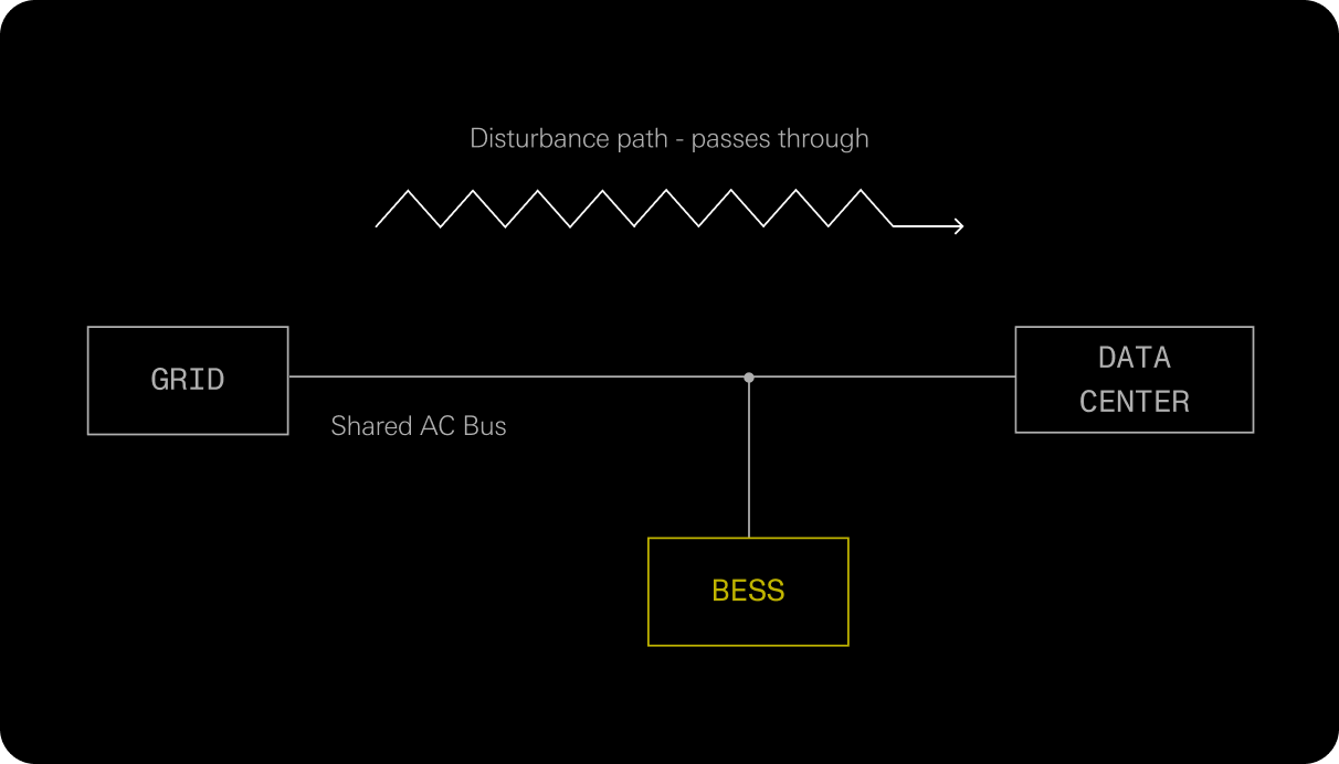
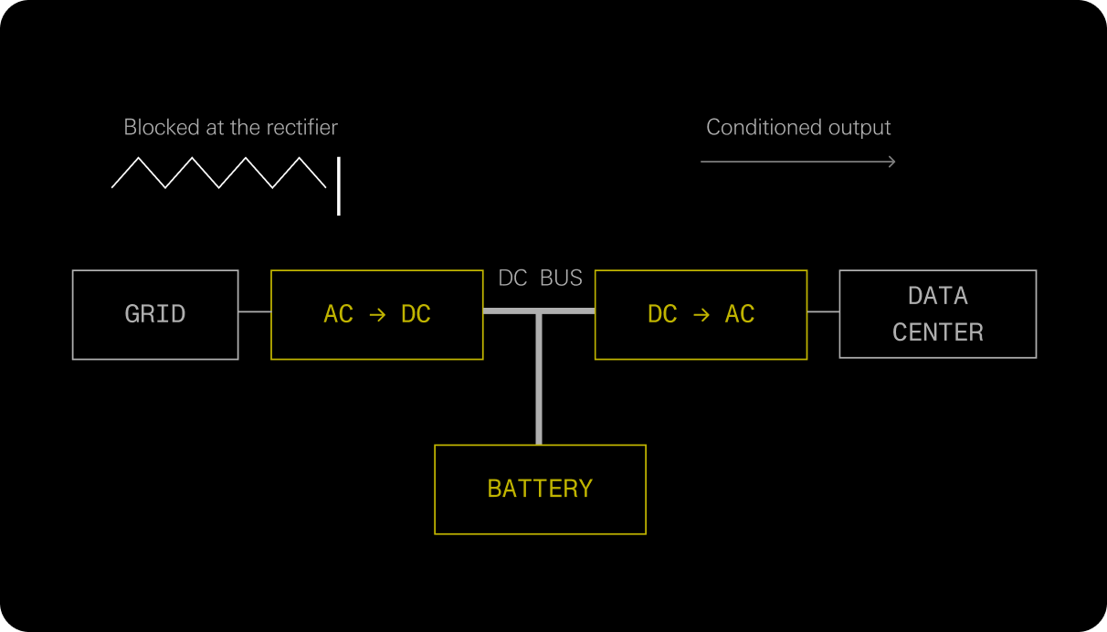
The two systems can use similar batteries and similar inverters. The difference is topological: whether the battery sits beside the load on a shared bus, or between the grid and the load in the power path.

Parallel BESS: power architecture diagram from the technical brief
One shared bus. Grid disturbances reach the load, and load transients reach the grid in both directions, in real time.

Parallel BESSGrid-interactive · GFL / GFM / Hybrid

  • The BESS operates in parallel with the grid.
  • It can run grid-following, grid-forming full-time, or switch between modes; the control mode doesn't change the topology.
  • The load is never electrically isolated from upstream disturbances.
Defining trait

Direct coupling between grid dynamics and the IT load.

ON.energy AI UPS: power architecture diagram from the technical brief
AC → DC → AC. Everything upstream is converted to DC and rebuilt as a clean waveform on the other side.

ON.energy AI UPSMV AI UPS™ · Double conversion

  • Full electrical decoupling between grid and load.
  • The battery is integrated on the DC bus for energy buffering.
  • Proprietary controls actively smooth AI-driven load fluctuations.
Defining trait

Stable output, independent of upstream grid disturbances.

03 Normal operation

When the GPUs swing

Training workloads don't ramp politely. Megawatt-scale steps arrive in milliseconds, thousands of times a day. How each architecture handles them is a matter of physics, not tuning.

Response-time figures for parallel BESS configurations throughout this brief are estimates based on industry research.

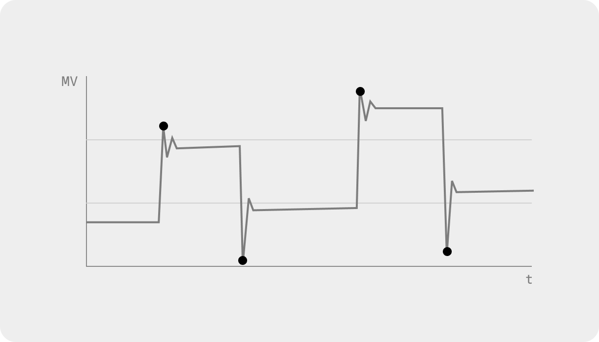
Parallel BESS: power architecture diagram from the technical brief
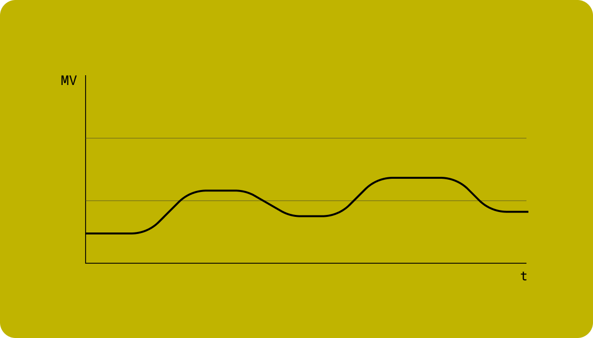
Draw at the meter through GPU ramps (illustrative): Each step lands with an excursion.

Parallel BESSFast, but reactive

On paper, a fast inverter can react within a quarter cycle, roughly 4 ms at 60 Hz. Realistic grid-forming response runs 1-2 cycles (16-33 ms). Reactive means after. In that window, every large ramp produces short-duration surges and sags. Voltage and frequency excursions propagate to the load; load transients propagate to the grid; harmonic and transient-instability risk compounds.

Acceptable forStrong transmission-level grids; Loads that tolerate downtime.

Risky forWeak grids; Islanded microgrids; High-density AI workloads.

AI UPS: power architecture diagram from the technical brief
Same ramps behind AI UPS (illustrative): The grid sees shaped transitions, nothing else.

AI UPSBuffered, not reactive

The DC link buffers continuously. There is no detection step to wait on. Grid-side draw follows a controlled ramp-rate setpoint, and upstream transients have no electrical path to the load. The result is a deterministic, smooth power draw, with sub-cycle disturbances eliminated in both directions.

AI UPS behaves as a power-conditioning firewall, not a responsive but exposed system.

04 Grid disturbance

One event, five endings: the zero-voltage sag

A fault upstream pulls voltage at the point of interconnection to zero. The grid operator expects the full load back the instant voltage recovers. The servers expect power that never blinks. A parallel BESS has to choose which promise to keep—and each fix for that choice creates the next problem.

NOT COMPLIANT

Configuration 01

Protect the load

BESS sized for the entire facility load

  1. t = 0 ms

    Grid voltage collapses, zero-voltage sag.

  2. t = 4–30 ms

    The facility plant controller detects the sag and islands the data center onto its microgrid.

  3. t = 30–100 ms

    Grid-forming BESS response kicks in to back up the IT loads.

  4. t = 100 ms +

    The facility runs in island mode.

When voltage returns, the facility's load is missing from the grid, which is not ERCOT compliant. Protecting the load created an interconnection violation.

Compute dropped

Configuration 02

Protect compliance

BESS sized for the entire facility load

  1. t = 0 ms

    Grid voltage collapses.

  2. t = 4–30 ms

    Loads disconnect. The facility sheds its compute.

  3. t = 30–150 ms, after voltage returns

    The BESS charges at the full facility rating, standing in for the load the grid expects to see.

  4. t = 150 ms +

    Compute reconnects and ramps back up. Chillers and mechanical loads reconnect. The BESS must ramp its charging down at exactly the rate the loads ramp up until everything is back online and the BESS returns to standby.

Compliance held; the compute did not. And the charge-absorb-and-ramp-down choreography is complex to model and harder still to operate at scale.

Cooling at risk

Configuration 03

Add a low-voltage UPS

Parallel BESS + LV UPS on the IT load

  1. t = 0 ms

    Grid voltage collapses.

  2. t = 4–30 ms

    The IT load rides through on LV UPS battery power, disconnecting from the upstream source.

  3. t = 100 + ms

    VFDs on the cooling-system pumps give out and stop.

  4. t = 1 + s

    IT racks begin to heat — possibly until over-temperature alarms or failure.

  5. after voltage returns

    The BESS ramps up charging to absorb the demand the IT load is no longer drawing from the grid; the cooling system returns to operation.

  6. t = 150 ms +

    The same reconnect-and-rebalance choreography as Configuration 02.

Compute rode through; cooling did not. Reconnection still runs the Configuration 02 choreography: the BESS charges in place of the transferred IT load, then ramps down in step as loads return to the grid.

COOLING AT RISK

Configuration 04

Add coolant storage or more LV UPS

Parallel BESS + LV UPS + coolant tanks and/or chiller and pump LV UPS

  1. t = 0 ms

    Grid voltage collapses.

  2. t ≥ 4 ms

    The IT load rides through on LV UPS. Racks stay cool on LV-UPS-backed pumps drawing from large coolant tanks for up to a few minutes or on additional LV UPS capacity powering both chillers and pumps.

  3. after voltage returns

    The BESS ramps up charging to preserve grid-code compliance until the LV UPS units switch back to grid power. Compute, chillers, and mechanical loads reconnect while the BESS ramps its charging down in step, until everything is back online.

  4. throughout

    The system remains operational without disturbance.

It works; three added layers later, and complexity, cost, and facility footprint have increased significantly. Each layer brings its own failure modes.

AI UPS

Configuration 05

Nothing to transfer, nothing to choreograph

Zero transfer events. No dependence on grid-compliance logic or external UPS systems. The IT load and the cooling systems run continuously, without interruption.

  1. t = 0 ms

    Grid voltage collapses.

  2. t = 0 ms

    The load remains powered. It was decoupled all along; there is nothing to detect and nothing to transfer.

  3. t = 0 → ∞

    AI UPS maintains stable output and stands by to ramp grid consumption back within milliseconds of voltage recovery.

05 Constraints

Why a parallel BESS can't tune its way out

The configurations above aren't engineering missteps. They are the corners that a parallel topology is boxed into by four constraints pulling against each other.

Grid operator requirements

The load must come back instantly

Where reconnection is required, the load must return to the grid immediately upon recovery. A parallel BESS cannot fully isolate the load without creating compliance issues.

The LV UPS fallback

Riding through shifts the burden

A LV UPS is required to keep compute alive through transfer events. However, the load it carries is no longer drawing from the grid when voltage returns, so the BESS must charge in its place and choreograph the handback.

Sizing

Undersizing fails both ways

If the BESS is smaller than the total facility load: without a LV UPS it may not power the cooling loads; with one, it may not meet interconnection obligations. Either way, the system becomes non-compliant.

Cooling sensitivity

~100 ms is all the cooling gets

Cooling loops may trip after roughly 100 ms of lost supply: a thermal-instability risk for AI infrastructure measured in seconds, not minutes.

06 System cost

What the workaround stack costs

Escaping the constraints means stacking systems: parallel BESS, plus LV UPS, plus coolant storage or additional LV UPS. The stack carries three kinds of cost.

Architecture complexity

  • Dual protection schemes
  • Multiple operating modes
  • More points of failure
  • More detail, complexity, and IP required for EMT model qualification

Capital & efficiency

  • Redundant power-conversion systems
  • The lower efficiency typical of LV UPS
  • Additional switchgear and controls

Operational risk

  • Coordination failures during transfer events, grid restoration, and load rebalancing
  • LV UPS maintenance and mid-life replacement; LV UPS lifetimes can run shorter than the data center's, while BESS batteries carry warranties up to 20 years
  • Inherent fire safety and project risk from batteries inside an occupied, manned facility

07 Side by side

Comparative summary

Parallel BESS and double-conversion AI UPS comparison
DimensionParallel BESSAI UPS — Double Conversion
Load isolationNoYes
Sub-cycle transientsPresent (4–30 ms)Eliminated
Ramp-rate controlReactiveDeterministic
Grid-disturbance ride-throughConditionalInherent
Cooling stabilityAt risk during eventsMaintained
Interconnection complianceComplexSimplified
Need for LV UPSLikely requiredNot required
System costHigh, with hybridizationLower integrated cost

08 Interconnection

The model the grid sees

Interconnection is where architectural complexity becomes schedule. A parallel hybrid facility presents the grid with a portfolio of interacting behaviors: islanding and reconnection logic, transfer switches, and the charge-and-ramp choreography above. Every behavior adds detail, complexity, and disclosed IP to EMT model qualification, and every reconnection is its own event to model and defend.

The double-conversion facility reduces to one simple inverter model for load-flow and EMT studies of the entire facility's interconnection, a representation already approved in ERCOT.

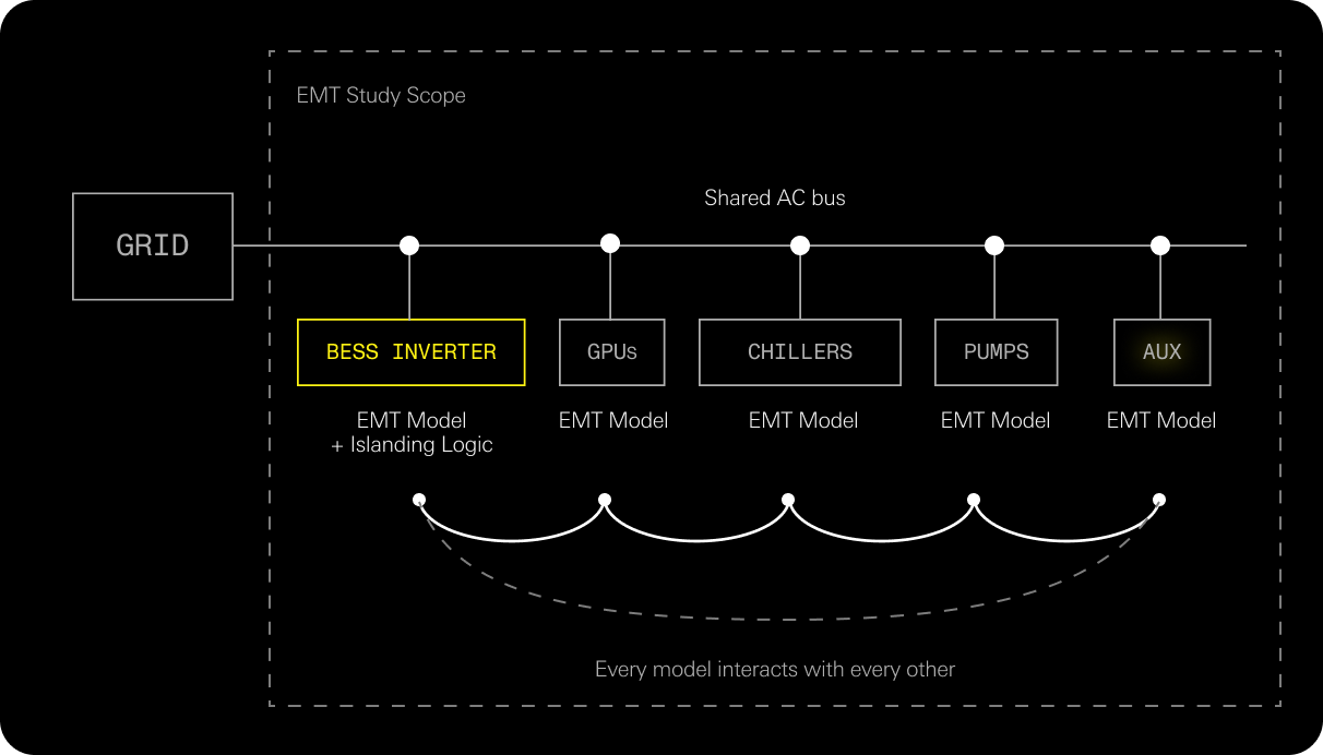
Model the bus and everything on it: power architecture diagram from the technical brief

Model the bus and everything on itParallel BESS · EMT Study Scope

The load shares the bus with the grid, so the study must capture all of it: the BESS inverter with its islanding and reconnection logic, plus the dynamic behavior of GPUs, chillers, pumps, and every other piece of equipment—each its own EMT model, each qualified against the new large-load rules.

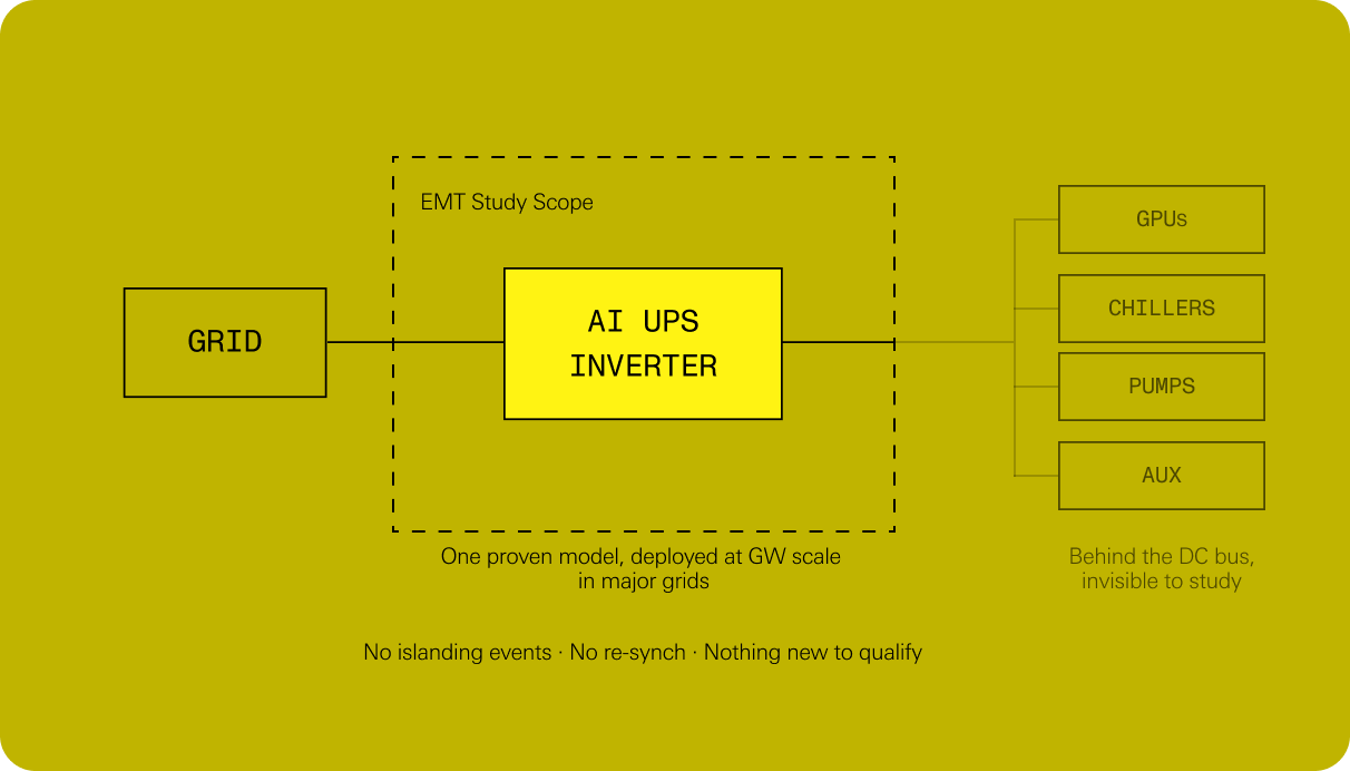
Model one inverter: power architecture diagram from the technical brief

Model one inverterON.energy AI UPS · EMT Study Scope

The study models one inverter: a platform already deployed at gigawatt scale in most major grids. Everything behind the DC bus is buffered; the load never appears in the model.

From the grid's perspective, the facility never disconnects, never back-feeds, never re-synchronizes. It is one rate-controlled, unidirectional load.

To the interconnection queue, an AI factory behind an AI UPS is the simplest asset there is: a BESS that only charges.

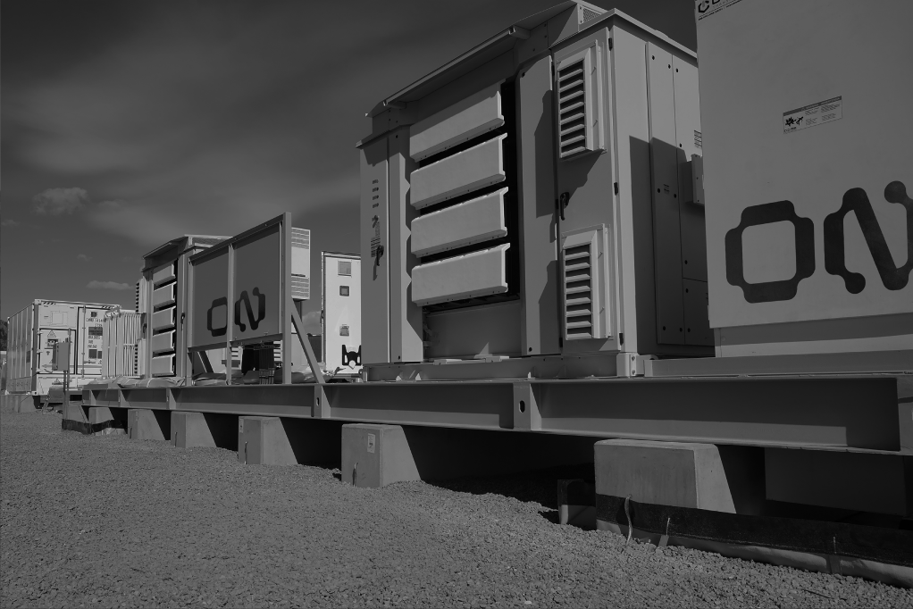
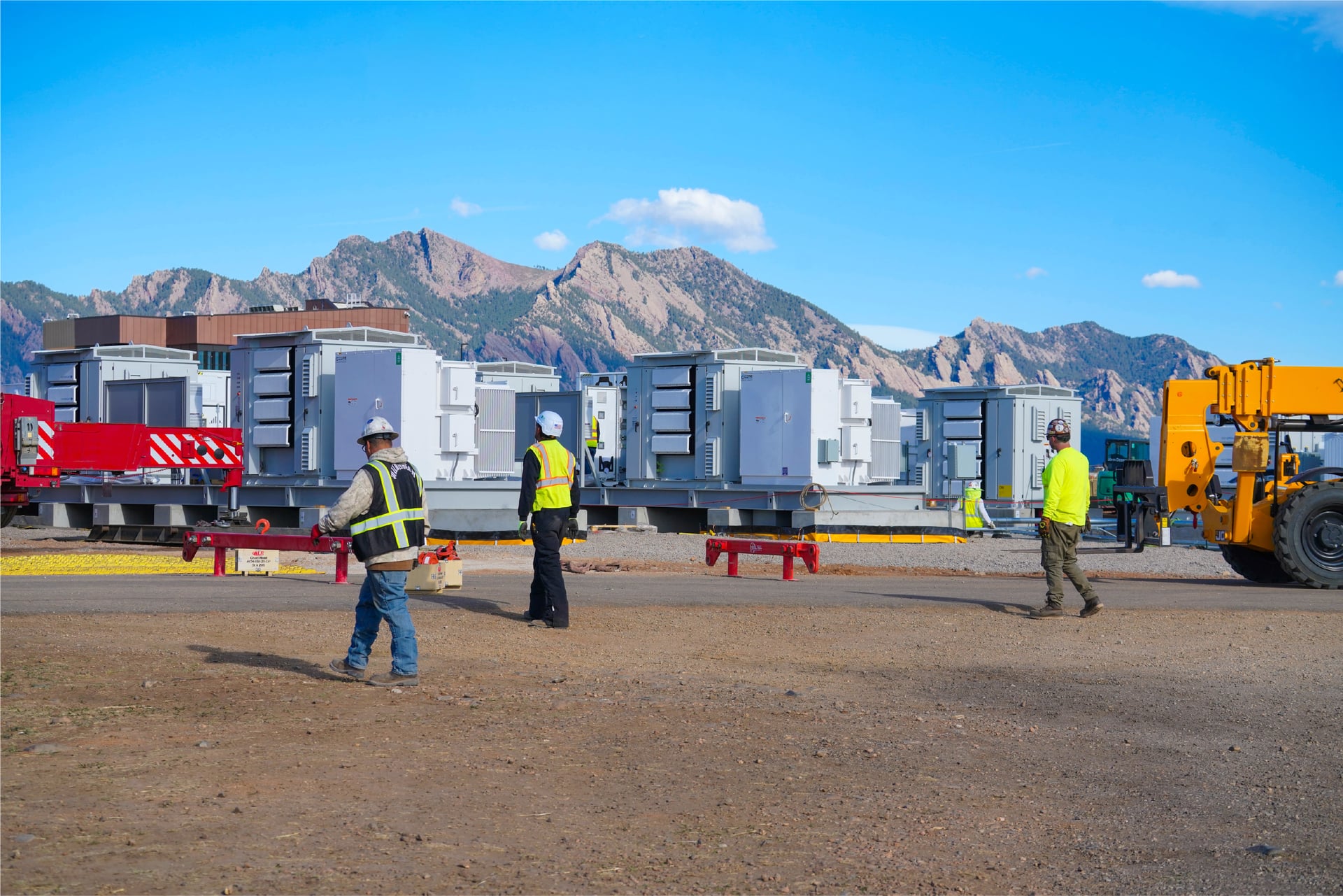
ON.energy power infrastructure installation with a field team and mountain backdrop

Conclusion

A different architecture, not a different tuning

Parallel BESS architectures extend grid-connected systems toward a UPS-like role, but they fundamentally lack electrical isolation. The consequences follow directly: transient exposure during high-ramp AI workloads, operational conflict with grid interconnection requirements, and growing reliance on additional protection layers.

The ON.energy AI UPS delivers UPS-grade power quality (IEC 62040-3 Class 1 compliant), buffers AI load volatility at the source, eliminates transfer events and power interruptions, and simplifies the system architecture while reducing total cost.

A parallel BESS competes in steady state. In transient performance, disturbance resilience, and system simplicity, AI UPS is a fundamentally different architecture.